
"What's the voltage of an NMC pouch cell?" doesn't have a single-number answer, and that's usually where the confusion starts. A cell reads differently depending on whether you're measuring it at rest, mid-discharge under load, sitting at full charge, or approaching the point where the BMS should already have cut it off. If you're specifying a cell for a pack design, all four of those numbers matter, and they're not the same number.
This piece walks through what each voltage figure actually means for NMC pouch cells, how it compares to LFP, and how single-cell voltage turns into a pack-level system voltage once you start stacking cells in series.
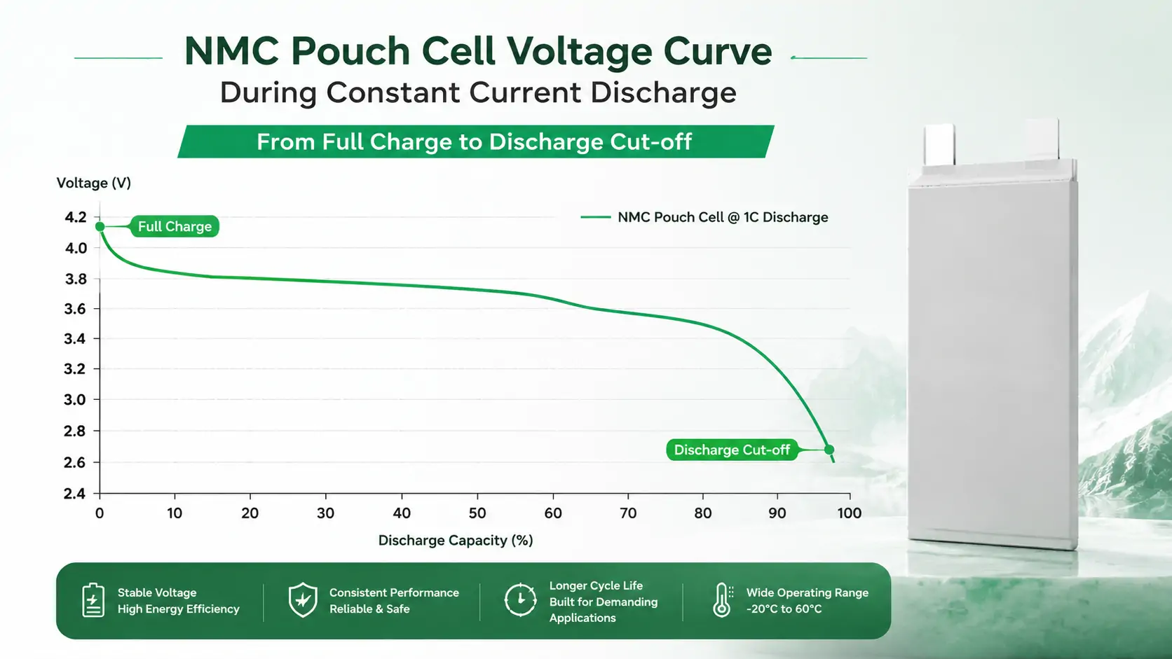
NMC Cell Voltage Quick-Reference Chart
Four numbers answer most of what people are searching for when they type "NMC cell voltage" into Google. Here they are in one table — worth screenshotting or printing for the bench.
| Voltage Point | Typical Value (per cell) | What It Tells You |
|---|---|---|
| Rest voltage (open-circuit, ~50% SOC) | 3.70V – 3.75V | What a meter reads with no load connected — the closest single number to "state of charge," but only at rest |
| Full-charge voltage | 4.20V (up to 4.35V–4.40V on high-voltage variants) | Upper cutoff — where the charger should stop pushing current |
| Common nominal voltage | 3.6V – 3.7V | The datasheet figure used for pack-voltage math (S × nominal), not a live reading |
| Recommended discharge cutoff | 2.75V – 3.0V | Lower limit — where the BMS should stop discharge to avoid copper dissolution at the anode |
Rest voltage moves with state of charge, not just with full/empty. A rough open-circuit reading across a discharge:
| State of Charge | Typical Rest Voltage (per cell) |
|---|---|
| 100% | 4.15V – 4.20V |
| 75% | 3.85V – 3.90V |
| 50% | 3.70V – 3.75V |
| 25% | 3.50V – 3.55V |
| 10% | 3.30V – 3.40V |
| 0% (at cutoff) | 2.75V – 3.00V |
These are typical ranges for standard NMC pouch cells, not a universal constant — confirm the exact curve against the specific cell's datasheet before using it for SOC estimation.
Nominal Voltage: An Average, Not a Fixed Reading
Nominal voltage is the voltage figure printed on the datasheet and the one most engineers use for quick pack-voltage math — but it's not a value you'll actually read off the cell terminals for most of a discharge cycle. It's closer to a time-averaged midpoint of the voltage curve across a full discharge at a moderate rate.
For NMC chemistry, nominal voltage typically sits in the 3.6V–3.7V range. Terminal voltage will actually read higher than that right after a full charge and lower than that as the cell approaches empty — nominal voltage is the number that makes pack-voltage arithmetic simple, not the number you'll see on a meter at any given moment. Browse the current NMC pouch cell lineup to see how nominal voltage and capacity vary model to model within this range.
Full Charge Voltage (Upper Cutoff)
Full charge voltage — sometimes called the charge cutoff or upper voltage limit — is the point where the charging circuit should stop pushing current into the cell. For standard NMC chemistry, this is typically 4.2V per cell; some high-nickel or high-voltage NMC variants are rated up to 4.35V–4.4V, but that's a chemistry- and cell-specific figure, not a universal NMC number.
Charging past the rated upper cutoff isn't a soft limit you can push a little for extra capacity. Overcharging NMC accelerates cathode degradation and, in a worst case, drives the cell toward thermal instability — which is exactly why a properly configured BMS enforces this cutoff in hardware, not just firmware logic that a buyer might assume is "close enough."
Discharge Cutoff Voltage (Lower Limit)
The discharge cutoff is the opposite boundary: the voltage below which the cell should stop delivering current. For NMC, this typically falls between 2.75V and 3.0V per cell, depending on the specific cell design.
Pulling a cell below its rated cutoff — even briefly, even under a heavy load spike — risks copper dissolution at the anode current collector, which permanently damages capacity and can create an internal short risk on subsequent charge cycles. This is also why voltage sag under high C-rate pulses matters: a cell that reads well above cutoff at rest can dip below it momentarily during a hard pulse if the BMS isn't accounting for load-dependent sag, not just static voltage.
NMC Voltage Curve: What the Readings Mean Under Load
The voltage figures above are all rest, or open-circuit, values — read with no current flowing. The moment a load is applied, terminal voltage drops below that rest value, and how far it drops depends on current draw, internal resistance, and temperature, not on state of charge alone.
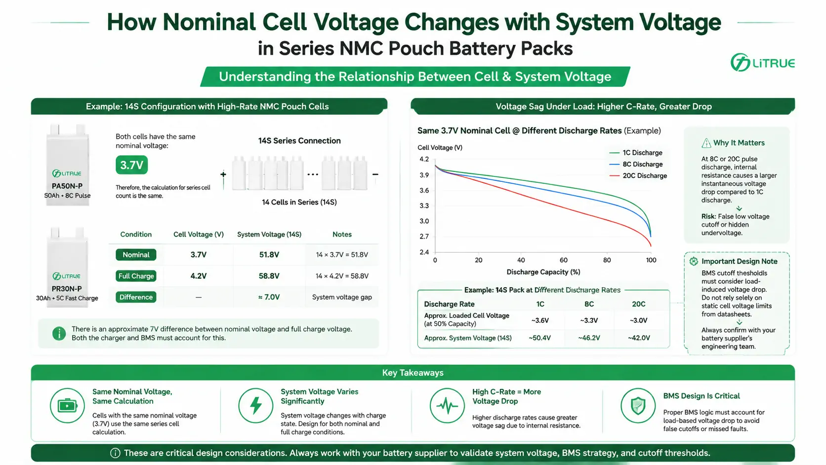
This drop is IR drop — the cell's internal resistance acting like a small series resistor. Pull 1C from a cell and you'll see a modest sag; pull 5C or 8C and the same cell can sag several hundred millivolts lower, even though the actual remaining capacity hasn't changed. A cell reading 3.4V under a hard pulse might still be sitting at 60% SOC at rest — the reading looks low because of the load, not because the cell is nearly empty.
Temperature compounds this. Internal resistance rises as a cell gets colder, so the same current draw produces a bigger voltage sag at 0°C than it does at 25°C. A pack that reads comfortably above cutoff on a warm bench can sag closer to the limit outdoors in winter, under an identical load profile.
The practical risk is misreading an instantaneous, loaded voltage as a state-of-charge number. If a BMS or a manual voltage check treats a sagged reading as "nearly empty," it can trigger a false low-voltage cutoff mid-run — a risk that shows up often in drone and UAV battery packs, where discharge pulses are heavy and short. SOC should be estimated from rest voltage, or from coulomb counting under load, not from a single voltage reading taken while current is flowing.
NMC Cell Voltage Range by Series Configuration
Once you know the per-cell numbers, series count (S) just multiplies them. The table below covers the series counts that come up most often in BMS design, drone packs, and multi-cell battery packs — 1S single-cell circuits up through 12S and 14S packs.
| Configuration | Nominal Voltage (3.7V/cell) | Fully Charged (4.2V/cell) | Discharge Cutoff (2.75V/cell) |
|---|---|---|---|
| 1S | 3.7V | 4.2V | 2.75V |
| 2S | 7.4V | 8.4V | 5.5V |
| 3S | 11.1V | 12.6V | 8.25V |
| 4S | 14.8V | 16.8V | 11.0V |
| 12S | 44.4V | 50.4V | 33.0V |
| 14S | 51.8V | 58.8V | 38.5V |
This table uses 3.7V nominal and a 2.75V cutoff as the baseline — the middle of the typical NMC range covered earlier in this article. Cells like the 30Ah NMC Pouch Cell High C-Rate 5C Fast-Charging (PR30N-P) use this same 3.7V nominal baseline, so the series-count math above applies directly. If your cell's datasheet specifies 3.6V nominal or a 3.0V cutoff instead, the math scales the same way — just substitute the per-cell figure and multiply by S; the gap between nominal and full-charge system voltage is what your charger and BMS both need headroom for, and it grows wider as series count increases.
NMC vs. LFP: Why the Voltage Numbers Differ
NMC and LFP are both lithium-ion chemistries, but their voltage characteristics — and the shape of their discharge curves — are meaningfully different, which is exactly why pack voltage math changes depending on which chemistry you pick.
| Parameter | NMC | LFP |
|---|---|---|
| Nominal Voltage | ~3.6V – 3.7V | ~3.2V |
| Typical Charge Cutoff | ~4.2V (up to 4.35V–4.4V for high-voltage variants) | ~3.65V |
| Typical Discharge Cutoff | ~2.75V – 3.0V | ~2.5V – 2.8V |
| Discharge Curve Shape | More sloped — voltage drops progressively across the discharge | Very flat — voltage stays close to nominal until a sharp drop near empty |
That flat LFP discharge curve is a double-edged detail worth knowing: it makes state-of-charge estimation from voltage alone much harder for LFP than for NMC, because most of the LFP curve sits within a narrow voltage band. NMC's more sloped curve actually makes voltage-based SOC estimation more straightforward — one of the practical trade-offs that sits alongside the more commonly cited energy-density and cycle-life differences. Confirm the exact cutoff and nominal figures against the specific cell's datasheet before finalizing a design — these are typical ranges, not universal constants across every NMC or LFP cell on the market.
Getting the voltage window right is only half the selection problem — series/parallel configuration, discharge C-rate, and duty cycle all interact with it. Send our team your target series/parallel count (SxP), voltage window, and discharge rate, and we'll recommend a cell or pack configuration for it — reach out to the LiTrue engineering team to get started.
From Cell Voltage to System Voltage
Pack, or system, voltage is a straightforward function of series count: system voltage ≈ nominal cell voltage × number of cells in series (S). Parallel strings (P) add capacity and current capability without changing the nominal voltage.
Take a 3.7V-nominal high-rate NMC pouch cell like the 50Ah High-Rate NMC Pouch Cell 8C Pulse (PA50N-P): a 14S configuration puts nominal system voltage at roughly 51.8V, while full-charge system voltage (14S at ~4.2V per cell) sits closer to 58.8V — a gap of about 7V between nominal and full-charge that a charger and BMS both need to account for. Any 3.7V-nominal NMC pouch cell scales the same way — the series-count math doesn't change with capacity or C-rate, only the nominal and cutoff figures do.
This is also where high-rate cells add a wrinkle: at 8C or 20C pulse discharge, internal resistance losses cause a larger instantaneous voltage sag under load than the same cell would show at 1C. If your BMS discharge cutoff is set purely off a static per-cell voltage table without accounting for load-dependent sag, a hard pulse can trip a false low-voltage cutoff — or worse, mask an actual undervoltage event. This is a design detail worth confirming with the cell supplier's engineering team, not something to assume from the datasheet's rated voltage window alone.
For More on Pouch Cell Construction
Voltage behavior is only part of what makes a pouch cell suited to a given application — the stacked-electrode construction itself affects rate capability and consistency in ways that interact directly with the voltage sag behavior described above. See what is a pouch cell lithium battery for the underlying construction details.
FAQs
How do I confirm the exact voltage window before selecting a cell?
Request the cell's datasheet and confirm four numbers explicitly: nominal voltage, charge cutoff (upper limit), discharge cutoff (lower limit), and the rated C-rate those cutoffs were tested at. A datasheet that lists a cutoff voltage without stating the test C-rate is incomplete — voltage sag at your actual operating rate can differ meaningfully from the rated test condition.
Does nominal voltage change as the cell ages?
The rated nominal voltage on the datasheet doesn't change, but the voltage curve shape does shift with cycle aging — internal resistance increases, which means more voltage sag under the same load and a shorter effective time spent near nominal voltage per cycle. This is one reason BMS voltage cutoffs are typically set with margin rather than exactly at the cell's absolute rated limits.
Why does my pack voltage read lower than the calculated nominal value under load?
This is voltage sag from internal resistance (IR drop) — normal behavior under any current draw, and more pronounced at high C-rates or as a cell ages. Static nominal voltage math (S × nominal cell voltage) gives you a baseline; actual under-load voltage will read lower, more so as current draw and cell resistance both increase.
Is a higher charge cutoff voltage always better for capacity?
No — pushing charge cutoff higher than the cell's rated limit trades a small capacity gain for a real reduction in cycle life and, past a certain point, a genuine safety margin reduction. Rated cutoff voltages already reflect the manufacturer's tested balance between usable capacity and long-term stability; exceeding them isn't a free capacity increase.
Do parallel-connected cells need to be voltage-matched before assembly?
Yes. Cells wired in parallel should be closely matched in resting voltage and internal resistance before assembly — a significant mismatch causes an uncontrolled current flow between cells at connection time, and ongoing imbalance that shortens pack life and complicates BMS balancing.